Utilizing EPOGS
EPOGS is a new automated curvilinear overset grid generation software developed by NASA. We will use it in this tutorial to generate a nearbody grid commensurate with that just created in the prior scripting tutorial, then generate a far-field using LAVA's octFarField utility and connect the grid using LAVA's connectivity task.
The 'from-scratch' EPOGS gridding process involves first running the egads2srf
and then pogs CGT executables, stopping them at checkpoints, reviewing certain
files for issues, then potentially creating new files or altering existing ones
to tweak values before continuing from each checkpoint. This process is well
tutorialized within CGT 3.0 and will not be discussed here in depth: the
presented scripted application of EPOGS within this tutorial's CRM project
directory structure exemplifies how to include EPOGS once this checkpoint
process has been undergone and all settings/files have been properly set/built.
egads2srf requires a 'solid' CAD geometry as an input, which involves taking
an existing geometry file and processing it correctly within applicable CAD
software. A solid version of the CRM body-wing-tail geometry has been provided
in the geom directory. Eventually, surface grids will be grown on each face of
this solid, as well as from each of its edges and on each of its nodes. Thus, a
solid with the fewest faces is preferable.
The calls to egads2srf and pogs are within a nearBody_EPOGS component
script directory, and have settings which were pre-determined to work as
desired. Thus, the actual building of the grid will seem very similar to the
scripted version on the surface.
Building the CRM Project Grid with an EPOGS Near-body
To build the starting nearBody CRM project grid, simply make a new sub-folder
in the 'run' directory (e.g. 'RANS'), then run the run_buildGrid_EPOGS.sh
script from within that folder. This file is shown below. Remember to properly
set the LAVACGTToolsDir, LAVA_EXE_DIR, LAVA_EXE_SUFFIX, and
OMP_NUM_THREADS environmental variables in envVars.sh first.
This run script first calls a nearbody grid generation script in the same form as the scripting tutorial within which the EPOGS method is employed to generate the nearbody component. Then the farField is generated and the two are combined.
# Run egads2srf and pogs, and write its BC file in LAVA format,
# housed within the component script format.
# ---------------------------------------------------------------------------- #
baseDir=$( cd -- "$( dirname -- "${BASH_SOURCE[0]}" )" &> /dev/null && pwd )

source $baseDir/envVars.sh

$baseDir/buildProjectGrid_nearBody_EPOGS.tcl

mv -f grid.in    nearBodyGrid.x
mv -f grid.sur   nearBodyGrid.sur
mv -f grid.bc.in nearBodyGrid.bc
# ---------------------------------------------------------------------------- #

# Build the farField using the octFarfield exe.
# First copy over the input script and the surface representation it requires
# as a starting point.
# ---------------------------------------------------------------------------- #
cp $baseDir/geom/NEARBODY_REF.plt .
cp $baseDir/auxFiles/LAVA_octFarField.yaml .

$LAVA_EXE_DIR/octFarfield.$LAVA_EXE_SUFFIX LAVA_octFarField.yaml

rm NEARBODY_REF.plt LAVA_octFarField.yaml check.plt farFieldGrid.x.cart \
   octFarfield.dat
# ---------------------------------------------------------------------------- #

# use the mergeGrids exe guild combine the nearBody and farField -> final grid.
# ---------------------------------------------------------------------------- #
$LAVA_EXE_DIR/mergeGrids.$LAVA_EXE_SUFFIX nearBodyGrid.x farFieldGrid.x grid.x

cp -f nearBodyGrid.sur grid.sur
# ---------------------------------------------------------------------------- #
Let's look at the main nearbody_EPOGS component grid script. Below is a portion
of the main nearbody_EPOGS.tcl script which calls the egads2srf exe.
CRM_EPOGS.stp is the solid geometry file. The first two arguments state that
y plane symmetry exists, and that face 22 should be removed: if egads2srf was
to be check-pointed part way through and inspected, there would be 21 on-body
surface faces, and one in-body symmetry plane face to close the half-fuse which
must be removed. The maxsr and dswall growth parameters are set to be the
same as the scripted grids. maxa, maxe and maxc are geometric parameters
used to identify what edges are 'small' (in this case tag trailing edges), and
npmin is set to be the number of points on those small edges (matching the
scripted grid trailing edges). stenqual is setting the fringe interpolation
requirement to be the same as LAVACurv's.
104     exec egads2srf -i        CRM_EPOGS.stp \
105                    -isym     2 \
106                    -frm      22 \
107                    -maxa     4.0 \
108                    -maxe     0.5 \
109                    -maxc     0.002 \
110                    -maxsr    $Par(sr) \
111                    -npmin    25 \
112                    -dswall   $Par(ds,wall) \
113                    -stenqual 1.0 \
114                    > egads2srf.out
After the surface has been assessed pogs can be run as shown below. Due to
known bug in 3.0, this is performed in two steps, first writing out the surface
grids and then restarting from them to grow the volumes. The input file
CRM_EPOGS.001.pogs.i is an output from egads2srf. frc asks to reconstruct
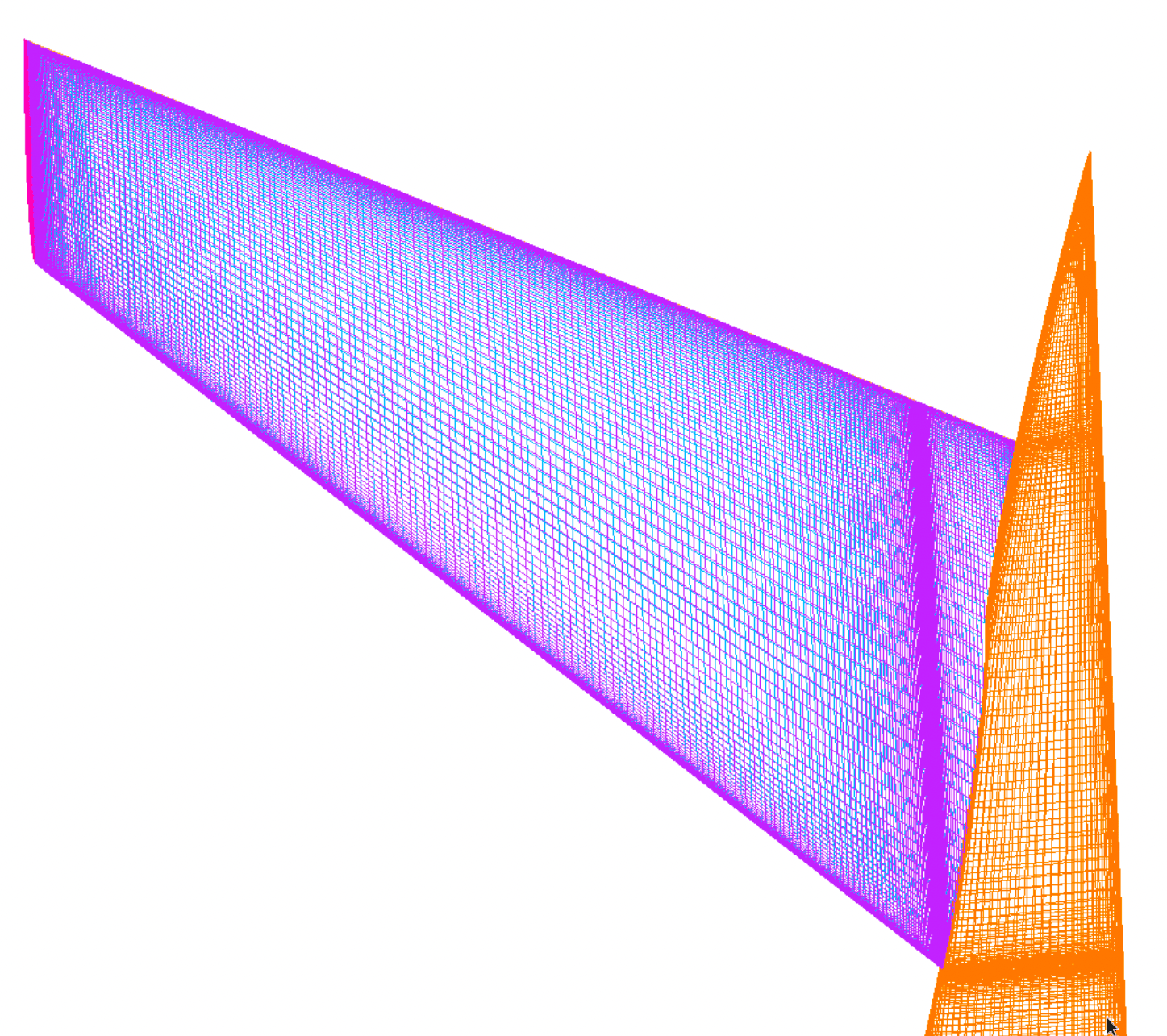
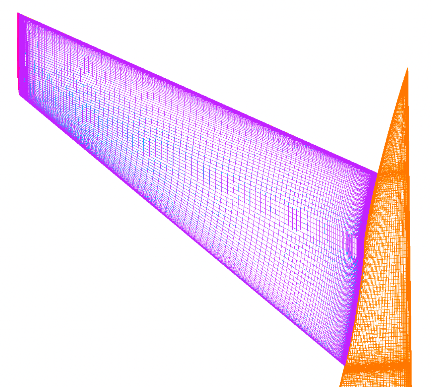
the upper and lower tail surface. A figure of the initial tail face grids is
also shown below. The distribution of the surfaces doesn't align well with the
fuse, and so the intersection of the tail and fuse is used as a guideline to
re-make it.
122     exec pogs -frc    19,20 \
123               -arcse  0.15 \
124               -klayer $Par(klayer) \
125               -stop   go.sur \
126               < CRM_EPOGS.001.pogs.i \
127               > pogs.surfGen.out
.
.
.
131     exec pogs -frc    19,20 \
132               -arcse  0.15 \
133               -klayer $Par(klayer) \
134               -start  volgen \
135               -stop   nb.vol \
136               < CRM_EPOGS.001.pogs.i \
137               > pogs.surfRst.out
After the surface and volume grids are built, they are scaled (the input solid geometry was in inches and LAVA needs meters) and renamed.
143     GedAddRemoveIB nb.vol nb.vol.clean 0
144     GedScale       nb.vol.clean $fileN.vol 0.0254
145     GedScale       go.sur $fileN.sur 0.0254
No manually-generated cutters are required, but the BC file must still be
written. pogs outputs a generic bc file in LAVA format without component names,
but also outputs a fomoco.i file which has proper BC information. Eventually,
this functionality will be corrected, but for now the appropriate BCs have been
transcribed into nearbody_EPOGS.BC.tcl.
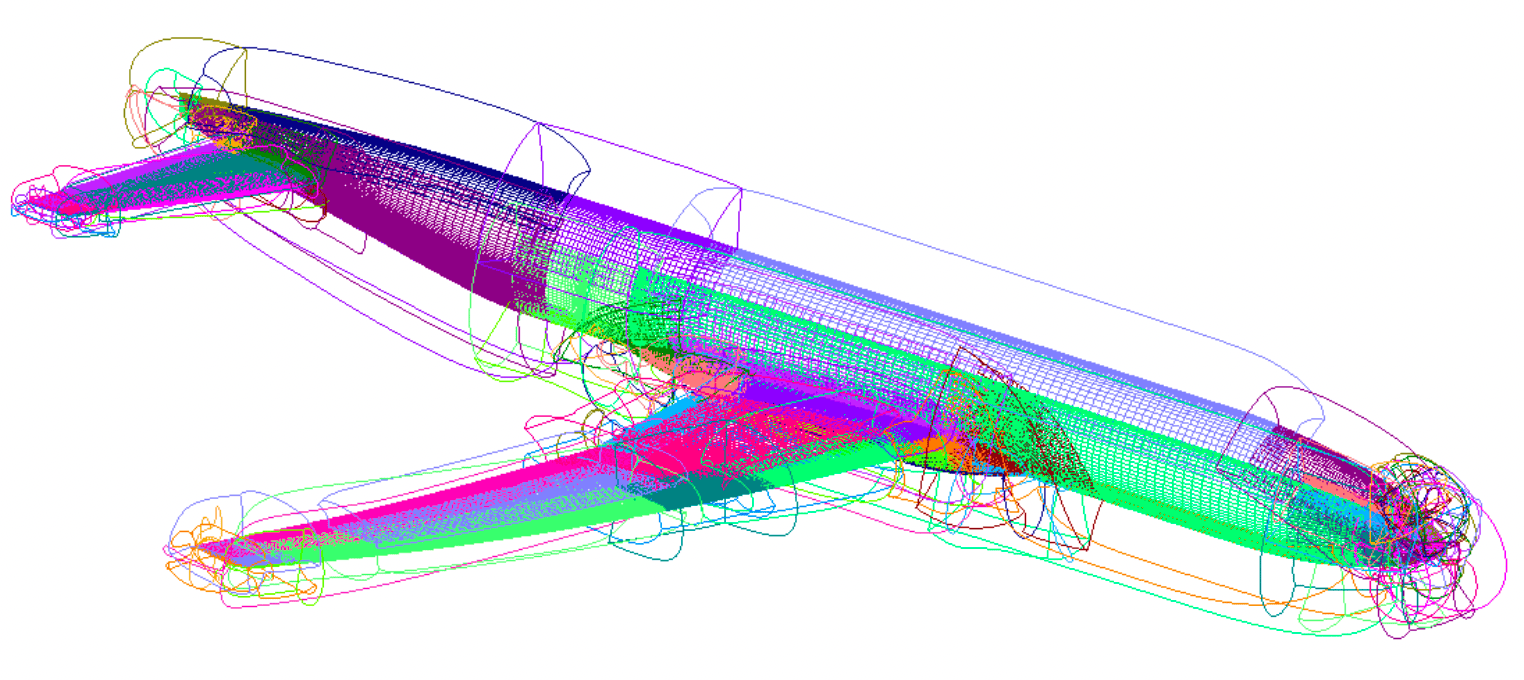
The EPOGS nearbody grid is shown below, and consists of 78 grids and ~226 million nodes compared to the 40 and ~125 millions nodes manually scripted. The farField grid is the same as the scripted case, resulting in a combined set of 239 grids with ~344 million nodes.
Running Connectivity
To run connectivity, follow the instructions in the connectivity tutorial,
keeping in mind that you must use the init_connectivity_EPOGS.sh script
instead of init_connectivity.sh. Running connectivity with 55 threads takes
roughly 13.3 seconds for this case.
The main addition to the LAVA_connectivity_EPOGS.yaml file copied in and
renamed is a symmetry plane explicit cutter (shown below) which states that all
nodes below the y=0 plane should be blanked. This is needed for this case
because several of the pogs generated grids grow past this plane, i.e.
outside the computational domain. Feel free to comment this cutter, re-run
connectivity, and see where they arise.
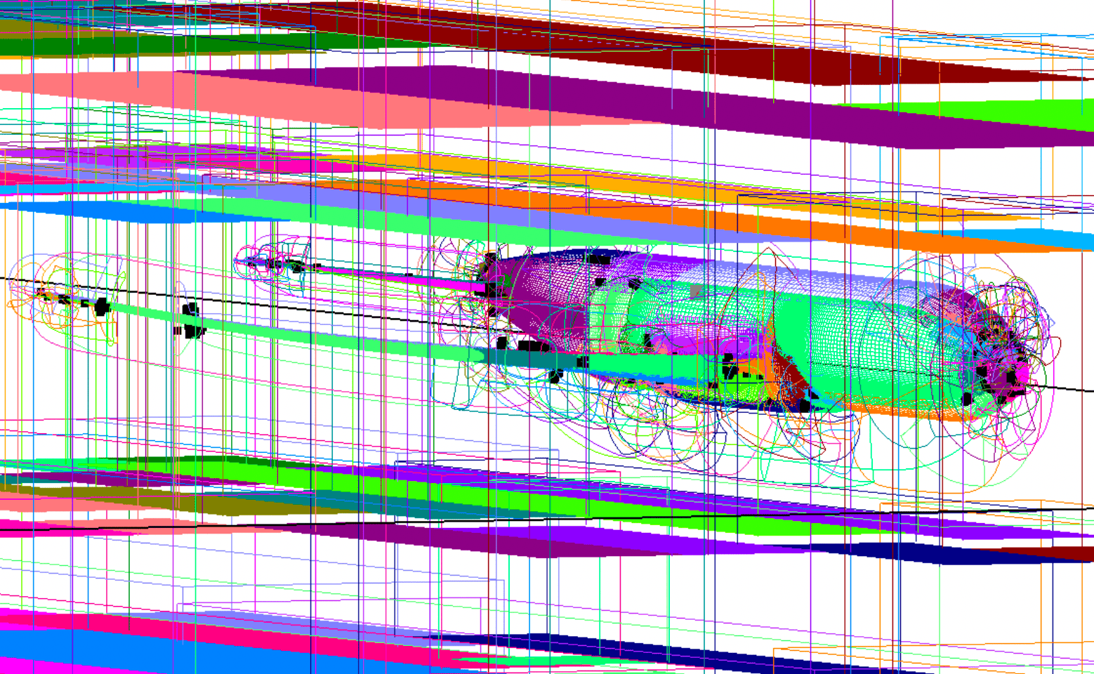
As shown in the final, connected grid below as black dots, there are 9502
orphans in the final grid. These stem from a lack of proper overlap of surface
grids and/or volume growth splay. Current work on EPOGS seeks to remedy reasons
such orphans can occur. The current strategy to fix these orphans would be to
pop out and script alterations to specific grids within grid.x, insert them
back in, and then re-run connectivity. This process has not been undergone for
this tutorial, but is documented in the CGT 3.0 tutorials. This grid will not
be used for solutions in the following tutorials, but could be substitued for
the traditional script-generated one if desied. For this case, the results are
similar.