
High-Resolution Launch Environment Simulations
Overview
NASA’s Kennedy Space Center (KSC) recently redesigned and rebuilt their main flame deflector (MFD) at Launch Complex 39B. During late stages of the rebuild, the KSC team realized that the gaps between the MFD and the trench wall, and the gaps between the steel plates of the MFD itself could allow hot plume gases and strong acoustic waves to affect structures under the MFD, posing launch safety and maintenance concerns. A team of experts from the NASA Advanced Supercomputing (NAS) Division was called in to apply high-resolution computational fluid dynamics (CFD) to help identify thermal, pressure, and flow environments on and around the geometrically complex MFD.
Over the last decade, the NAS Division’s Launch Ascent and Vehicle Analysis (LAVA) team has helped KSC engineers with redesigning the MFD shape and position for both the Space Launch System (SLS) and a range of commercial rockets. In previous work, the LAVA team investigated both ignition overpressure waves and thermal conjugate heat transfer simulations of the MFD, the mobile launcher, and the tower, including umbilical hardware and other key components of the launch pad. The MFD design team’s innovative new deflector design uses easily replaceable and durable shingled steel plates, but gaps between the plates result in small flow paths to the back side of the MFD. Leaving the gap raised issues and construction was stopped, prompting a call to the NAS team as the recognized experts to perform necessary analyses.
Project Details

The focus of these simulation results, obtained with advanced post-processing, will be on evaluating small gaps between the MFD metal plates and the flame trench wall, in addition to small gaps in the MFD main slope, between individual metal plates. Analysis of both thermal and pressure environments are being conducted.
NAS Division experts completed large-scale, high-end CFD simulations of highly detailed as-built pad geometry, which required the development of appropriate boundary conditions, meshing, and lift-off information. The CFD simulations were performed with the NAS-developed LAVA code; post-processing was conducted using statistical tools from the LAVA framework and high-end, custom visualization techniques developed within the division. The extremely complex geometric topologies were easily handled at full fidelity using the high-order accurate LAVA immersed boundary Cartesian Navier-Stokes approach.
In addition, thermal environment simulations were conducted using LAVA’s unstructured CFD code, utilizing a boundary layer resolved mesh and conjugate heat transfer within the MFD metal. The simulations are some of the largest conducted at NAS—the LAVA Cartesian simulation contained over 555 million cells, over 500,000 timesteps, and utilized over 4,000 cores on the NAS facility’s newest modular supercomputer.
Results and Impact
These CFD results are being used to guide project engineers in evaluating real-time design decisions as the MFD project progresses. Results will allow the MFD contractors to confidently continue the project, and will help NASA reduce the mission risk—averting issues and potentially saving significant amounts of time and money. This collaboration also represents a great opportunity to advance NASA Ames Research Center’s key expertise in the launch acoustics area, and to further improve the division’s in-house software.
Why HPC Matters
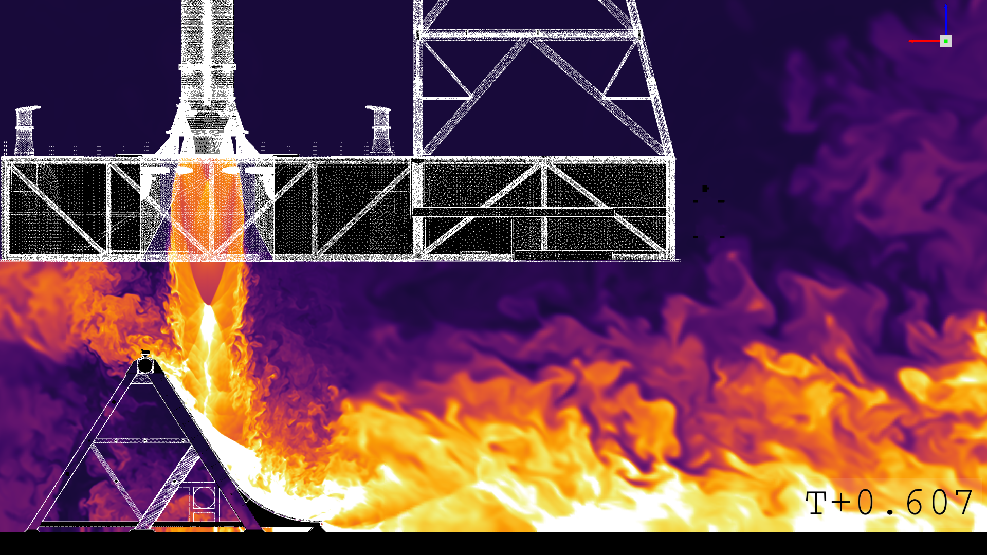
This high-resolution simulation required approximately five weeks of simulation time using up to 4,000 Intel Xeon Skylake cores on Electra. Because the simulation was unsteady, hundreds of terabytes of data were generated for each calculation. Data analysis and visualization were conducted by NAS visualization experts using custom in-house software and high-performance systems.
More Information
- See the poster for this demonstration (PDF, 1.4MB). As shown in the NASA booth at SC18.
michael.f.barad@nasa.gov Cetin Kiris, NASA Ames Research Center
cetin.c.kiris@nasa.gov