The AMD Turin nodes of the new Athena cluster are installed in a module located less than a mile from the main NAS building.
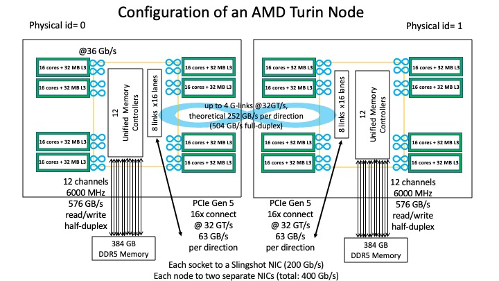
This is a simplified configuration of an AMD Turin node with two EPYC 9745 processors (i.e., two sockets) and a total of 768-gigabyte (GB) DDR5 memory with 24 memory channels (12 per socket).
The EPYC 9745 processor uses the AMD Zen 5c microarchitecture. Each processor contains 128 cores in eight Core Complex Dies (CCDs, each shown in a green box). Each CCD contains a single Core Complex (CCX) with 16 cores and a shared 32 MB L3 cache. The cores run with a base clock of 2.4 GHz, an all-core boost clock of 3.45 GHz and a maximum boost clock of 3.7 GHz.
Note: The Zen 5c microarchitecture (manufactured on a 3 nm process) is a compact variant of the Zen 5 microarchitecture (manufactured on a 4 nm process) and therefore can pack more cores per CCX. Zen 5c emphasizes efficient throughput while Zen 5 emphasizes peak performance.
Each processor has one I/O die (IOD, enclosed in a yellow box) which utilizes AMD's Infinity Fabric Technology to interconnect among CCDs, memory and I/O:
Each node connects to two Cray Slingshot-11 Cassini network interface cards (NICs) through a PCIe 5.0 link per socket. Each NIC is connected to a Slighshot-11 Rosetta switch. The NICs and switches run at a rate of 200 Gb/s, which provide an aggregate of 400 Gb/s (per direction) for each node.
Main Differences Between the NAS Turin Processors and Milan Processors:
- CCD and CPU cores: Turin has more cores per socket and more advanced features.
Milan uses the Zen 3 microarchitecture and has 64 cores/socket partitioned in 8 CCDs (each with 8 cores). Turin uses the Zen 5c microarchitecture and has 128 cores/socket partitioned in 8 CCDs (each with 16 cores).
Turin has more accurate branch prediction, instruction pipeline optimization, and more integer and floating-point units.
Milan supports Advanced Vector Extensions up to AVX2 (256 bits). Turin adds supports for AVX-512 with full 512-bit floating-point data paths.
- Cache and Memory: Turin has larger L1 data cache, larger L2 cache, faster memory speed, more memory channels, and higher per-socket and per-core memory bandwidth than Milan, but smaller L3 cache/core and smaller memory size/core.
|
Milan |
Turin |
| L1 data cache |
32 KB/core |
48 KB/core |
| L2 cache |
512 KB/core |
1 MB/core |
| L3 cache |
32 MB/8 core |
32 MB/16 cores |
| Memory Size |
256 GB/64 cores |
384 GB/128 cores |
| Memory Speed |
3200 MHz |
6000 MHz |
| # of Memory Channels |
8 |
12 |
| Memory Bandwidth |
204.8 GB/s /64 cores |
576 GB/s / 128 cores |
- Interconnect: Turin has a faster network to connect the two sockets in a node and to connect outwards.
The IOD in Milan utilizes PCIe 4.0 technology (running at a rate of 16 GT/s per lane) to provide support for Infinity Fabric within a node and for interconnecting outwards. Turin utilizes PCIe 5.0 technology (running at a rate of 32 GT/s per lane).
Additional information about the NAS Turin nodes is provided below.
CPU Core
Unlike the Zen 4 microarchitecture which supports AVX-512 instructions by processing two 256-bit vectors in sequential clock cycles, Zen 5/5c comes with full 512-bit floating point data paths which allow data to be read into the CPU in a single clock cycle. In addition, a Basic Input/Output System (BIOS) firmware setting can direct the processor to execute AVX-512 instructions using either one 512-bit vector (for better performance) or two 256-bit vectors (for better power efficiency). The NAS AMD Turin nodes are configured to use the 512-bit vector for AVX-512 instructions.
With the use of the full 512-bit data path and floating-point fused multiply-add units, each Zen 5/5c core can deliver 32 double-precision floating-point operations (FLOPs) per clock cycle. Thus, a Turin 9745 processor can deliver 2.4 GHz x 128 cores/processor x 32 Flops = 9.8304 TFLOPS per processor which translates to 19.6608 TFLOPS per node.
The Zen 5/5c microarchitecture brings in some new instructions not available in earlier generations:
- MOVDIRI/MOVD64B: Move 4, 8, or 64 bytes as a direct store (to memory), bypassing caches.
- VP2INTERSECT: AVX-512 vector pair intersection to a pair of mask registers.
- VNNI/VEX: Extend AVX-512 Vector Neural Network Instructions (VNNI) to VEX encoding.
- PREFETCH[I]: Software prefetch of instruction lines into cache hierarchy.
For a complete list of instructions supported by Turin, run the cat /proc/cpuinfo command on a Turin node.
Through a BIOS setting, each core can have Simultaneous Multi-Threading (SMT) enabled to allow 2 separate hardware threads which share the corresponding core's L1 and L2 cache. To check the SMT setting on a Turin node, use the lscpu | grep "Thread(s) per core" command. When SMT is enabled, cat /proc/cpuinfo shows a total of 512 logical cores per NAS Turin node.
Compiler support for the AMD Turin processors:
- Cray compiler:
-march=znver5 or -march=cray-znver5 is available in Cray C compiler versions 19.0.0 and 20.0.0 (but not in Cray Fortran compiler).
- GNU compiler:
-march=znver5 is available in GNU compiler version 13.3 and 14.2.
- AOCC compiler:
-march=znver5 is available in AOCC compiler version 5.0.
- Intel Classic Fortran Compiler (ifort):
-march=core-avx2 -mavx512f -mavx512dq -mavx512bw -mavx512vl
For more information, read AMD EPYC 9xx5-Series Processors Compiler Options Quick Reference.
Cache Hierarchy
- op cache: 6K entries, private to each core; 16-way.
Note: An op cache is a specialized cache that stores pre-decoded micro-operations (uOps) which are the smallest units of instructions the CPU can execute. There are two op cache pipes; each can deliver 6 uOps simultaneously to the CPU's execution units in a single clock cycle (2 x 6-wide fetch/cycle), resulting in a total of 12 uOps instructions per cycle.
- L1 instruction (L1I) cache: 32 kilobytes (KB), private to each core; 64 bytes/line; 8-way; 2 x 32 bytes fetch per cycle.
- L1 data (L1D) cache: 48 KB, private to each core; 64 bytes/line; 12-way; support 2 loads and 1 store per cycle for 512-bit operation, otherwise, support 4 loads and 2 stores per cycle to/from the execution units.
- L2 cache: 1 MB, private to each core; unified (instruction/data); 64 bytes/line; 16-way; 64 bytes/cycle bandwidth to/from either L1I or L1D cache.
- L3 cache: 32 MB shared among 16 cores in a CCX; 64 bytes/line; 16-way; 32 bytes/cycle bandwidth to/from L2 cache.
Memory Subsystem
Turin places twelve unified memory controllers in the centralized I/O die. With a total of 12 memory channels each at the speed of 6,000 GHz, an 8-byte read or write taking place per cycle per channel results in a maximum total memory bandwidth of 576 GB/s per socket.
Each memory channel can be connected with up to two Double Data Rate fifth generation (DDR5) Dual In-line Memory Modules (DIMMs). For the NAS Turin configuration, each channel is connected to a single 32 GB DDR5-6400 registered DIMM (RDIMM) with error correcting code (ECC) support. This one-DIMM-per-channel configuration provides lower latency than the two-DIMM-per-channel configuration. In total, the amount of memory is 384 GB per socket and 768 GB per node.
Through BIOS, the processor and the memory channels in a socket can be set up as 1, 2 or 4 Non-Uniform Memory Access (NUMA) nodes. Currently, the front-end nodes are configured with NPS=1 (i.e., 1 NUMA node per socket, or 2 NUMA nodes per front-end node) and the compute nodes are configured with NPS=2 (i.e., 2 NUMA nodes per socket or 4 NUMA nodes per node).
Inter-Node Network
Currently, a total of 1,024 Turin nodes in the Athena cluster are configured with the HPE Cray EX4000 architecture as follows:
- 4 racks in the cluster (256 nodes/rack; note that racks are also known as cabinets).
- 8 chassis per rack (32 nodes/chassis).
- 8 compute blades per chassis (4 nodes/blade).
The hostname of each node is x100[0-3]c[0-7]s[0-7]b0n[0-3].
Note: We plan to add more racks to Athena in 2026.
These 1,024 nodes are connected as a single fabric using the Cray Slingshot-11 High Performance Interconnect (HPI) Network, where each node is connected to two Slingshot-11 Cassini NICs (on two separate dual-NIC Mezzanine cards), which in turn connect to two Slingshot-11 Rosetta Ethernet switches. The HPI possesses these features:
- HPC Ethernet: This is a specialized Ethernet network that maintains compatibility with existing Ethernet devices and protocols and is optimized with adaptive routing, congestion management, and quality of service.
- High radix switches: These are switches with large number of ports to allow for a high degree of connectivity among devices. Each Slingshot switch provides 25.6 Terabits/s (Tbps) of bi-directional bandwidth with 64 ports (in 32 jacks with 2 ports per jack), each capable of delivering 200 Gbps per direction.
- Dragonfly topology: A two-level dragonfly topology is a hierarchical network of switches divided into groups. Within a group, it is a local level network (L1), while between groups it is a global level network (L2). For the NAS Athena cluster:
- A group is a rack. With 4 racks in the system, there are 4 groups.
- A group contains 32 switches within a rack (4 per chassis).
- Within a group, an all-to-all topology is used.
- Each switch uses 31 out of the 64 ports to connect to the other 31 switches in the group (L1, local)
This results in a fully non-blocking network without internal contention, as every switch has a direct connection to any other switch in the same group. Due to the large number of connections needed at this level, copper cables are used rather than the more expensive optical cables.
- Each switch uses 16 ports to connect to 16 compute nodes (L0, edge)
Copper cables are also used to connect switches to NICs in compute nodes.
Note: Each compute node has two NICs to connect to two switches.
- Between groups, an all-to-all connection is also formed.
- The connection between each pair of groups is known as an arc.
At its current configuration with 4 racks, the Athena cluster is designed with 80 Quad Small Form-factor Pluggable - Double Density (QSFP-DD) optical cables per arc. Each cable is connected to a jack with 2 ports and delivers 400 Gbps unidirectional bandwidth (therefore, a 800 Gbps bidirectional bandwidth).
- The 80 QSFP-DD cables per arc are roughly evenly distributed among the 32 switches in a group.
Note: When more racks are added to Athena, the number of cables per arc will be reduced due to the limit of available ports for L2 network.
- The maximum number of switch-to-switch hops is 3 between any pair of nodes in the system.
Connecting Athena to the NAS Filesystems
The Athena cluster is connected via 28 InfiniBand router nodes, to the NAS InfiniBand HDR interconnect, and to the NAS I/O network where the filesystems are located.
References


