
| PEGASUS 5 User's Guide | ||
| Previous Section | Table of Contents | Next Section |
PEGASUS has been developed and tested on a number of unix and linux based systems. Every attempt has been made to conform to standard Fortran 90 conventions; therefore, compilation on other platforms with compliant Fortran 90 compilers should be straightforward.
To compile and install PEGASUS and all of the utility programs and scripts, follow these steps:
| configure --enable-mpi | To enable MPI parallel execution (See MPI Compilation below) |
| configure --disable-dp | To use 32-bit single-precision, the default is 64-bit double-precision |
| configure --enable-debug | To enable debug compiler flags and output |
| configure --with-ifort | Use Intel ifort compiler |
| configure --with-gfortran | Use gfortran compiler |
| configure --with-pgi | Use pgf90 Portland Group compiler |
| configure --with-mpif90 | Use mpif90 mpich2 compiler front-end |
| configure --with-bigendian | Use -fconvert=big-endian option with gfortran compiler |
| configure --with-byteswapio | Use -byteswapio option with pgi compiler |
| configure --installdir=DIR | Executables will be installed in directory DIR |
The executable will be named pegasus5.
It is recommended that PEGASUS be compiled and run in double precision
when viscous grids are used. Running viscous cases in single precision
has been seen to sometimes adversely affect the hole-generation process,
and in some cases can affect interpolation as well.
3.1.1 MPI Compilation
As of version 5.1g, PEGASUS5 has a parallel execution option which utilizes Message-Passing Interface (MPI) standard. This option must be enabled when the code is compiled. Use of the --enable-mpi configure option will produce a peg/Makefile which enables MPI, and will produce an executable named pegasus5mpi. See Section 4.2 for information about running pegasus5mpi.
3.2 User Inputs
Two types of input must be supplied: the volume grids, and the
standard input file. There are some utility codes, which are
described in Section 3.3, which help in the
preparation of this input. The details of these inputs are described
in this section.
The standard input file can either be directed to be read by the software
through stdin, as in:
pegasus5 < peg.i
or through a command-line argument:
pegasus5 -ifile peg.i
The individual volume grids are stored in a sub-directory within the project directory called X_DIR. See Section 3.5 for a description of the directory structure used by PEGASUS5 code. The grids are to be stored as unformatted, single-zone, PLOT3D grid files. These grid files are named "mesh_nameA.x", "mesh_nameB.x", etc, where mesh_nameA, mesh_nameB, ... correspond to the NAME variables in the $MESH namelists in the standard input file.
All of the user inputs to PEGASUS are read from the standard input. All inputs are in a form similar to FORTRAN NAMELISTS. The following is a list of all of the NAMELISTS defined in PEGASUS . Not all of these NAMELISTS have to be included in the input, and the order in which the NAMELISTS appear in the input does not matter. Most problems will only require input to be specified in the first three of these NAMELISTS:
In the namelists which require grid indices, negative numbers can be used to specify indices relative to the last index. For example, an index of j=-1 is equivalent to j=jmax, j=-2 is equivalent to j=jmax-1, etc.
$GLOBAL
This input sets global values for all meshes. Each record can be
overridden for any individual mesh by using the $MESH input. However, the mesh override is
limited to that individual mesh. For subsequent meshes, the global
values are used unless specifically overridden.
| Variable | Description | Default |
|---|---|---|
| ANGLE | Maximum angle, in degrees, between the surface normal of the projected point and the reference surface of projection. If greater than this angle, the projection is not allowed. | 30.0 |
| CENTER | Set equal to .TRUE. to create output for a cell-centered grid system. This causes the code to generate interpolation stencils for target coordinates at the cell centers using donor coordinates from the cell centers. The iblank array values will be cell-center based. If this option is selected, the user should also change the type of output file the OUTTYPE input variable. | .FALSE. |
| DISTANCE | A positive integer value that controls the maximum distance that a surface point can be projected. The input DISTANCE is the number of grid cells in the solid-wall normal direction used to compute the actual distance limit. | 20 |
| EPS | Tolerance of interpolation coefficient. Value of interpolation coefficients less than 0 and greater than 1.0 that is allowed for a converged stencil. Should be larger than machine epsilon. | 0.001 |
| EXCLBC | Set equal to .TRUE. if the points specified as boundary conditions are to be excluded as interpolated boundary points. (deferred implementation) | .TRUE. |
| FIXXSYM | If true, the code will attempt to force all of the stencils to be symmetric about the X=0 plane for all meshes which are detected to have bilaterally symmetric about the X=0 plane. | .FALSE. |
| FIXYSYM | If true, the code will attempt to force all of the stencils to be symmetric about the Y=0 plane for all meshes which are detected to be bilaterally symmetric about the Y=0 plane. | .FALSE. |
| FIXZSYM | If true, the code will attempt to force all of the stencils to be symmetric about the Z=0 plane for all meshes which are detected to have bilaterally symmetric about the Z=0 plane. | .FALSE. |
| FRINGE | Set equal to 1 for single fringe, 2 for double fringe, or 3 for triple fringe. | 1 |
| HBFRNG | Hole boundary fringe. Set equal to 1 for single fringe, 2 for double fringe, or 3 for triple fringe. | Value of FRINGE |
| INCORE | Specifies if main data (e.g., meshes, interpolation values, etc.) are kept incore (=.TRUE.) or written and read from file (=.FALSE.) | .FALSE. |
| LEVEL2 | Set equal to .TRUE. if "level 2" interpolation is to be performed. | .TRUE. |
| OBFRNG | Outer boundary fringe. Set equal to 1 for single fringe, 2 for double fringe, or 3 for triple fringe. If this value is not specified it takes on the value of FRINGE. | Value of FRINGE |
| OFFSET | Set to zero or a positive integer value. This value specifies the growth of the minimum hole created by all of the HCUT hole cutters. This value acts as the global default value for all individual MESH inputs. For example, if OFFSET=2, all field points within 2 indices of the hole are changed to hole points. See also the OFFSET input in the MESH namelist and the the HOFFSET input in the HCUT namelist. | 0 |
| ORPHFIX | Set equal to .TRUE., second fringe orphan points will be fixed, i.e., returned to field values. Certain flow solvers (e.g., OVERFLOW and INS3D) allow for mixed fringed conditions (single and double) and can use this option. | .TRUE. |
| TRIMFRNG | When set equal to .TRUE., the code will trim away all extra fringe points in the final iblank array saved in the XINTOUT file. The depth of each fringe point is determined by how many neighbor fringe points it has between itself and a hole or a grid boundary. The code will trim fringe points whose depth is greater than the input value of FRINGE. This option must be set to .TRUE. if this grid system will be used by Overflow together with grid adaptation. | .FALSE. |
| OUTER | Set equal to .TRUE. if automatic outer boundary specifications are to be performed. | .TRUE. |
| OUTTYPE |
This selects which type of interpolation-data output file will be written.
1=XINTOUT format, filename = XINTOUT 2=DCI format, two-dimensional, filename = pegasus5.dci 3=DCI format, three-dimneional, filename = pegasus5.dci If CENTER is true, then OUTTYPE must be set to 2 or 3. If CENTER is false, then OUTTYPE must be set to 1. |
1 |
|
START THRU |
The value of THRU can be changed to stop the execution before all
processing is complete. Set THRU to the name of a process to
have the program perform processing up to and including that process.
The value of START can be changed to force the program to start the execution beginning with a specific process. In this case the output files from a previous run from the processes preceeding START must exist in the WORK directory, or an error will occur. Normally this will not be necessary as the program will only run the processes when their output files are out of date with respect to their input. However, on certain very slow file systems, checking each of the existing output files can be very slow and START can speed up restart executions. The following are the possible process names to be used for setting START and THRU, in the order that they are executed: projection - project meshes with solid boundary conditions cellcenter - compute cell-center coordinates for each mesh adt - creates alternating digital tree for each mesh auto_hbound - creats automatic Cartesian hole cutters interpolate - interpolates each mesh-to-mesh combination man_hbound - creates surface cutter based on user inputs auto_cut - cuts holes using automatic Cartesian hole cutter man_cut - cuts holes using manual hole cutting comp_hole - assembles composite holes spec_int1 - specify points for "level 1" interpolation spec_level1 - pick "best" points for "level 1" interpolation level1fix - final processing of the level 1 interpolation spec_int2 - specifies points for "level 2" interpolation spec_level2 - pick "best" points for "level 2" interpolation xintout - produces the XINTOUT output file |
START='projection' THRU='xintout' |
| PROJECT | Set equal to .TRUE. if projection of solid wall boundary surfaces is to be preformed. | .TRUE. |
| SHIFT | This input is the same as the shift parameter in PROGRD and is used only if PROJECT=.TRUE., If equal to 1, move all points in J/K/L direction by same increment as surface point. If equal to 2, move nearest half of point in J/K/L direction by same increment as surface point. If equal to 3, hold opposite boundary fixed in J/K/L direction and redistribute interior points proportional to arclength distance from wall. | 3 |
| QCUTOFF | The level of quality that is accepted for a mesh. Interpolated boundary points with a value of quality below this level will be considered an "orphan" point and no interpolation information will be supplied. | 0.1 |
| QTOL | Tolerance band for quality. This value is used when selecting the "best" interpolated boundary point cell-interpolation stencil pair (see Section 2.3 and Figure 7). | 0.01 |
| XINCLUDE,YINCLUDE,ZINCLUDE | Range of X, Y, and Z values, respectively, to be included as boundary points. Composed of two values (a minimum and a maximum value) in each of the X, Y, and Z directions, respectively. | none |
This input controls the automatic hole cutting. It sets the global default used by individual $HCUT hole-cutters, and controls the option for automatic decomposition of the domain into multiple hole-cutters.
| Variable | Description | Default |
|---|---|---|
| HCUT | Set equal to .TRUE. if automatic hole cutting is to be performed. | .TRUE. |
| AUTOHCT | Controls automatic creation of multiple HCUT hole-cutters. Set to 0 to turn this feature off. Set to 1 to create one single automatic hole cutter. Set to N, where N>1, to automatically subdivide the entire domain into N HCUT hole-cutters. Note that for N>1, the automatically created hole-cutters will be added to any user-defined hole-cutters in the HCUT namelist inputs. | 1 |
| ADVCUT |
Integer value which controls the level of advanced hole-cutting used.
ADVCUT = 0: No advanced hole cutting is used. ADVCUT = 1: Aggressively blank fringe elements during painting phase. |
0 |
| CNX, CNY, CNZ | Integer dimensions of Cartesian grids (hole maps) used for hole cutting. | 512 |
|
CARTX CARTY CARTZ |
Each of these inputs is a pair of numbers to set the min and max boundaries
in the x, y, or z directions of the Cartesian boxes used in the automatic
hole cutting. If they are left at their default values, the
hole-cutting cartesian boundaries are set to extend just beyond the
surfaces making up the hole cutter. This input can be used to limit the extent of the of the volume in which holes can be blanked out by the hole-cutters, and in some instances, can be used to help close off leaks in a hole-cutting surface. |
-1.e30, 1.e30 |
| EXCLUDE | List of meshes that will not be cut by the AUTOHCT cutters. | none |
|
CUTPLVAL CUTPLDIR |
When AUTOHCT>1, these two inputs are used to define a list of cutting planes used in the initial sub-division of the domain into multiple HCUT hole-cutters. Each of these inputs should be a comma-separated list of one or more values, where each value designates a cutting plane. The CUTPLDIR list must contain integer values of 1, 2, or 3, indicting a x=constant, y=constant, or z=constant cutting plane, respectively. The CUTPLVAL list must contain real-number values indicating the value of the x, y, or z cutting plane. The cutting planes are used in the order they are listed. | none |
|
XCUTS YCUTS ZCUTS |
These three are logical variables which can be used to disallow splitting of the multiple HCUT hole-cutters in each of the three physical coordinate directions. For example, setting XCUTS=.FALSE. will not allow the domain to be split in an x=constant plane, only in y=constant and z=constant planes. | .TRUE. |
| INTERNAL | Logical variable which controls whether the automatically created hole cutters assume an internal or an external flow orientation. Set this to .true. for fully-enclosed internal-flow type geometries, ie - flow through an duct. Set to .false. for external-flow geometries, ie - flow around an airplane. | .FALSE. |
| Variable | Description | Default |
|---|---|---|
| QTOL | Tolerance band for quality for a. This value is used when selecting the "best" interpolated boundary point cell-interpolation stencil pair (see Section 2.3 and Figure 7). | 0.01 or QTOL specified in $GLOBAL |
| QCUTOFF | The level of quality that is accepted for a. Interpolated boundary points with a value of quality below this level will be considered an "orphan" point and no interpolation information will be supplied. | The value of QCUTOFF in $GLOBAL |
| HBFRNG | Hole boundary fringe. Set equal to 1 for single fringe, 2 for double fringe, or 3 for triple fringe. | The value of the next fringe value specified in the ascending order: FRINGE for this mesh, HBFRNG for $GLOBAL, FRINGE for $GLOBAL |
| OBFRNG | Outer boundary fringe. Set equal to 1 for single fringe, 2 for double fringe, or 3 for triple fringe. | The value of the next fringe value specified in the ascending order: FRINGE for this mesh, OBFRNG for $GLOBAL, FRINGE for $GLOBAL |
| ORPHFIX | Set equal to .TRUE., second fringe orphan points will be fixed, i.e., returned to field values. Certain flow solvers (e.g., OVERFLOW and INS3D) that allow for mixed fringed conditions (single and double) can use this option. | .FALSE. |
| PHANTOM | Setting PHANTOM=.TRUE. denotes this mesh is a "phantom" mesh, to be used only for hole cutting, and is not part of the final grid system. | .FALSE. |
| DATASURF | Setting DATASURF=.TRUE. denotes this mesh is a "data surface" mesh, to be used by the flow solver as a series of points to monitor the flow solution. The pegasus5 software mark all of the points in this type of mesh as fringe points, and will attempt to provide interpolation stencils for all these fringe points. Any orphan points will be turned into hole points. By default this type of mesh can be blanked by the automatic hole-cutting process. No boundary conditions can be assigned to any part of a data surface mesh. | .FALSE. |
| ALPHA, BETA, GAMMA | Euler angles (degrees) determining rotation of input meshes. ALPHA, BETA, and GAMMA are rotations about the Z, Y, and X coordinates, respectively. The coordinates of a mesh are transformed in the following sequence of operations: (1) scaling, (2) translation, and (3) rotation. | 0.0 |
| EPS | Tolerance of interpolation coefficient. Value of interpolation coefficients less than 0 and greater than 1.0 that is allowed for a converged stencil. Should be larger than machine epsilon. | Value of EPS in $GLOBAL |
| FRINGE | Set equal to 1 for single fringe, 2 for double fringe, or 3 for triple fringe. | Value of FRINGE in $GLOBAL |
| JINCLUDE, KINCLUDE, LINCLUDE | Range of J, K, and L indices, respectively, to be included for boundary points. Composed of two values (a starting and an ending value) in each of the J, K, and L directions, respectively. | none |
| NAME | Name of mesh to which NAMELIST record refers (must be any alpha-numeric characters with no special symbols). A NAME is a string not exceeding ICHAR characters. | none |
| SCALE | Mesh scaling factor. The original mesh coordinates are multiplied by the scaling factor. The coordinates of a mesh are transformed in the following sequence of operations: (1) scaling, (2) translation, and (3) rotation. | 1.0 |
| XINCLUDE, YINCLUDE, ZINCLUDE | Range of X, Y, and Z values, respectively, to be included for boundary points. Composed of two values (a minimum and a maximum value) in each of the X, Y, and Z directions, respectively. | none |
| XR,YR,ZR | Point (in translated and scaled coordinates) about which input mesh is to be rotated. The coordinates of a mesh are transformed in the following sequence of operations: (1) scaling, (2) translation, and (3) rotation. | 0.0 |
| X0,Y0,Z0 | Mesh translation factors. These factors are added to the original mesh coordinates. The coordinates of a mesh are transformed in the following sequence of operations: (1) scaling, (2) translation, and (3) rotation. | 0.0 |
| OFFSET | Set to a positive integer value, zero or greater. This value specifies the increase of the minimum hole that was created by an automatic hole cutter in this mesh. For example, if OFFSET=2, all field points within 2 indices of the hole are changed to hole points. | Value of $GLOBAL OFFSET. |
|
OFFSTJ OFFSTK OFFSTL |
Similar to the OFFSET input, except these grow the minimum hole only in one of the computational directions. This directional hole expansion is applied after the uniform hole expansion using the OFFSET input. | 0 |
| PROJECT | Logical variable which controls whether or not solid-wall points in this mesh will actively project themselves onto other solid-wall surfaces in other meshes. Even it this is set to .FALSE., this meshes solid walls may be used as a reference surfaces for other meshes to project onto, unless this mesh is listed in the PEXCLUDE list for all other meshes. | Value of $GLOBAL PROJECT. |
| SHIFT | This input is the same as the shift parameter in PROGRD and is used only if PROJECT=.TRUE., If equal to 1, move all points in J/K/L direction by same increment as surface point. If equal to 2, move nearest half of point in J/K/L direction by same increment as surface point. If equal to 3, hold opposite boundary fixed in J/K/L direction and redistribute interior points proportional to arclength distance from wall. | 3 |
| ANGLE | Maximum angle between the surface normal of the projected point and the reference surface of projection. If greater than this angle, the projection is not allowed. | 30.0 |
| DISTANCE | A positive integer value that controls the maximum distance that a surface point can be projected. The input DISTANCE is the number of grid cells in the solid-wall normal direction used to compute the actual distance limit. | 20 |
| PINCLUDE | Names of meshes that are to be included for projection with this mesh. | All meshes. |
| PEXCLUDE | Names of meshes that are to be excluded from projection with this mesh. | No meshes. |
This input is like the BCINP namelist in the OVERFLOW flow solver. This namelist specifies all of the boundary conditions for each mesh. PEGASUS uses this information to automatically cut holes (based on the specification of the solid walls), and to automatically determine the outer boundary points which will require interpolation. It also uses these boundary conditions to determine certain mesh topologies, such as o-grid periodic meshes, 2D meshes, and symmetry planes.
| Variable | Description | Default |
|---|---|---|
| ISPARTOF | Name of MESH for which these boundary conditions apply. | None |
| IBTYP | List of boundary condition types
-1 = dummy solid wall: used as a solid wall for hole-cutting, but these points will still be added to the list of outer-boundary interpolation points 1 - 8 = Solid wall 10 = O-grid periodicity (apply to first or last plane) 11 = Symmetry in X 12 = Symmetry in Y 13 = Symmetry in Z 14 = Axis (J around) 15 = Axis (K around) 16 = Axis (L around) 17 = Symmetry with no reflection plane 20 = Point-wise matched block boundary 21 = 2-D condition in Y (apply to one face) (3 planes supplied at Y=-1,0,1) 22 = Axisymmetric in Y, (apply to one face) (3 planes supplied, +/- 1 deg rotation about X) 30 = Outflow (extrapolation) 31 = Characteristic condition 32 = Supersonic/subsonic inflow/outflow 33 = Specified pressure outflow 35 = Outflow (1st-order extrapolation) 40 = Impose freestream 41 = Nozzle inflow 42 = Prescribed Q 43 = Prescribed Q with slow start 44 = actuator disk 45-46 = prescribed Q/inflow-outflow condition 47 = Freestream/characteristic condition 49 = Default (no change) 51 = C-grid flow-through (specify one side) (J is C-direction) 52 = C-grid flow-through (specify one side) (K is C-direction) 53 = C-grid flow-through (specify one side) (L is C-direction) 54 = Fold-over cut flow-through (fold-over in J) 55 = Fold-over cut flow-through (fold-over in K) 56 = Fold-over cut flow-through (fold-over in L) 57 = C-grid at a wall (apply wall first) (J is C-direction) 58 = C-grid at a wall (apply wall first) (K is C-direction) 59 = C-grid at a wall (apply wall first) (L is C-direction) 61 = Blank out region (set IBLANK=0) 70 = Copy to 71 = Copy from 81 = Slotted wind-tunnel wall 82 = Slotted wind-tunnel wall 86 = Wind tunnel exit |
None |
| IBDIR |
List of index directions:
1 = positive J direction -1 = negative J direction 2 = positive K direction -2 = negative K direction 3 = positive L direction -3 = negative L direction |
None |
| JBCS | list of beginning j-indices | None |
| JBCE | list of ending j-indices | None |
| KBCS | list of beginning k-indices | None |
| KBCE | list of ending k-indices | None |
| LBCS | list of beginning l-indices | None |
| LBCE | list of ending l-indices | None |
| XSYM | symmetry at X=0.0 | 1 if ibtyp=11
0 otherwise |
| YSYM | symmetry at Y=0.0 | 1 if ibtyp=12
0 otherwise |
| ZSYM | symmetry at Z=0.0 | 1 if ibtyp=13
0 otherwise |
| X2D | 2-dimensional in X
supply 3 planes in X=-1,0,1 |
0 |
| Y2D | 2-dimensional in Y
supply 3 planes in Y=-1,0,1 |
1 if ibtyp=21
0 otherwise |
| Z2D | 2-dimensional in Z
supply 3 planes in Z=-1,0,1 |
0 |
This input specifies a group of meshes that be used to create a hole cutting boundary, as well as which meshes will be cut by this hole cutting boundary. Entries in the $BCINP namelist must be present for this method to work. Both solid boundary and symmetry plane information must be present in the $BCINP namelist for the meshes that are used for the hole cutting boundary. If no $HCUT namelist groups are specified and HCUT is equal to .TRUE. (in namelist group $GLOBAL), a hole cutting boundary will be created from all solid boundaries in all of the $BCINP namelists, and this hole cutting boundary will cut a hole in all meshes. There can be zero to many $HCUT namelist groups specified in the user inputs.
| Variable | Description | Default |
|---|---|---|
| NAME | Name of hole cutting group (must be any alphanumeric characters with no special symbols). | none |
| MEMBER | List of meshes that make up a group. This group of meshes must define a completely enclosed volume. | all meshes |
| INCLUDE | List of meshes that will have minimum holes cut by this group of meshes. | all meshes |
| EXCLUDE | List of meshes that will not have minimum holes cut by this group of meshes. This input is only used when INCLUDE is not specified, i.e., when all meshes have been specified. | none |
| CNX,CNY,CNZ | Integer dimensions of Cartesian grids (hole maps) used for hole cutting. | CUTTER_CONTROL values of CNX, CNY, CNZ |
|
CARTX CARTY CARTZ |
Each of these inputs is a pair of numbers to set the min and max boundaries
in the x, y, or z directions of the Cartesian boxes used in the automatic
hole cutting. If they are left at their default values, the
hole-cutting cartesian boundaries are set to extend just beyond the
surfaces making up the hole cutter. This input can be used to limit the extent of the of the volume in which holes can be blanked out by the hole-cutters, and in some instances, can be used to help close off leaks in a hole-cutting surface. |
CUTTER_CONTROL values of CARTX, CARTY, CARTZ |
| CORNERO |
Integer variable composed of 8 digits whose value should be zero or one.
This controls the initial seeding of the 8 corners of the HCUT cartesian
map. A value of 1 indicates the corner is outside the solid body, and
a value of 0 indicates that the corner is inside the solid body. The
eight digits correspond to the corners as described:
10000000: corner at xmin, ymin, zmin |
11111111 |
| HOFFSET | Set to zero or a positive integer value. This value specifies the growth of the minimum hole created by this HCUT hole cutter in all meshes cut by this HCUT. For example, if HOFFSET=2, all field points within 2 indices of the hole are changed to hole points. See also the OFFSET input in the MESH namelist. | 0 |
|
HOFFSTJ HOFFSTK HOFFSTL |
Similar to the HOFFSET input, except these grow the minimum hole only in one of the computational directions. This directional hole expansion is applied after the uniform hole expansion using the HOFFSET input. | 0 |
| INTERNAL | Logical variable which controls whether the hole cutter assumes an internal or an external flow orientation. Set this to .true. for fully-enclosed internal-flow type geometries, ie - flow through an duct. Set to .false. for external-flow geometries, ie - flow around an airplane. | .false. |
| ADVCUT |
Integer value which controls the level of advanced hole-cutting used.
ADVCUT = 0: No advanced hole cutting is used. ADVCUT = 1: Aggressively blank fringe elements during painting phase. |
CUTTER_CONTROL value of ADVCUT |
If this input is not specified and OUTER is equal to .TRUE. (in namelist group $GLOBAL) outer boundaries for all meshes will be specified automatically. This means that meshes which do not have boundary condition data given in the $BCINP namelist will have outer boundary points specified on all mesh faces. The $OUTER namelist group should be used only if a specific group of meshes needs to be included or excluded from automatic outer boundary specification. Only one $OUTER namelist group can be specified.
| Variable | Description | Default |
|---|---|---|
| INCLUDE | List of meshes that will have outer boundaries determined from input boundary conditions. | all meshes |
| EXCLUDE | List of meshes that will not have the outer boundaries determined from input boundary conditions. This input is only used when INCLUDE is not specified, i.e., when all meshes have been specified. | none |
There are two types of BOUNDARY entities: a hole BOUNDARY and an outer BOUNDARY. To create a hole BOUNDARY, include the MHOLEIN variable in the namelist input and set it to a list of mesh names. Otherwise, if MHOLEIN is not included in the namelist, it will be an outer BOUNDARY. Any number of $BOUNDARY namelists may be included in the input.
A hole BOUNDARY has an associated set of one or more $SURFACE namelists, or a set of $BOX namelists. The $SURFACE namelist(s) define the surfaces that will bound the manual hole. The $BOX namelist(s) define a range of X, Y, and Z coordinates: any target grid points inside that range of coordinates will be turned into hole points.
A surface BOUNDARY has an associated set of one or more $SURFACE namelists, whose range of J, K, and L indices define an outer-boundary surface whose points require interpolation. In general, all outer-boundaries of meshes are determined automatically, and this is only used in special circumstances.
| Variable | Description | Default |
|---|---|---|
| CLOSED | When CLOSED=.TRUE., the BOUNDARY/SURFACE manual hole cut will be limited to cutting points inside the minmax box of the sum of the SURFACES. When CLOSED=.FALSE., the manual hole cut will be allowed to cut all points in the meshes in the MHOLEIN list. | .TRUE. |
| FAST | If .TRUE. then any BOUNDARY/SURFACE manual-hole cuts for this BOUNDARY will use a more efficient approximate-search algorithm. Manual hole cuts can be expensive when the SURFACES have many points cutting holes in very large meshes. Setting FAST=.TRUE. can reduce CPU time by a factor of 10. The FAST algorithm will not always produce the same holes as the original algorithm, particularly when the SURFACES are not smooth, have slope discontinuities, contain only fewer than six sides, or for CLOSED=.FALSE. boundaries. | .FALSE. |
| ISPARTOF | Mesh which contains boundary (must be any alpha-numeric characters with no special symbols). ISPARTOF is a string not exceeding ICHAR characters. | none |
| MHOLEIN | Meshes in which the named boundary causes holes. MHOLEIN's are specified as follows: MHOLEIN = 'mesh name 1', 'mesh name 2', etc. Each mesh name in MHOLEIN is a string not exceeding ICHAR characters. | none |
| NAME | Name of boundary (must be any alpha-numeric characters with no special symbols). A boundary name is a string not exceeding ICHAR characters. | none |
A SURFACE namelist must be associated with a BOUNDARY using the ISPARTOF variable.
| Variable | Description | Default |
|---|---|---|
| ISPARTOF | Boundary to which surface belongs (must be any alpha-numeric characters with no special symbols). ISPARTOF is a string not exceeding ICHAR characters. | none |
| JRANGE, KRANGE, LRANGE | Ranges of indices that define surface. Composed of two values (a starting and an ending value) in each of the J, K, and L directions, respectively. Maximum allowable ranges are: JRANGE: 1,JMAX KRANGE: 1,KMAX LRANGE: 1,LMAX | Default: none |
| MESHNAME | Name of mesh that contains the surface (ISPARTOF) (must be any alpha-numeric characters with no special symbols). NAME is used only for hole creation boundaries. Name is a string not exceeding ICHAR characters. | mesh name given in ISPARTOF for $BOUNDARY. |
| NVOUT | Direction of normal outward from hole. NVOUT is required only for hole creation boundaries. Allowable values are "+J", "-J","+K", "-K", "+L", and "-L". | none |
A BOX namelist must be associated with a BOUNDARY using the ISPARTOF variable.
| Variable | Description | Default |
|---|---|---|
| ISPARTOF | Boundary to which box belongs (must be any alpha-numeric characters with no special symbols). ISPARTOF is a string not exceeding ICHAR characters. | none |
| XRANGE,YRANGE,ZRANGE | Ranges of X, Y, and Z coordinates that define box. Composed of two values (a minimum and a maximum value) in each of the X, Y, and Z directions, respectively. | none |
| Variable | Description | Default |
|---|---|---|
| ISPARTOF | Mesh which contains region (must be any alpha-numeric characters with no special symbols). ISPARTOF is a string not exceeding ICHAR characters. | none |
| NAME | Name of region (must be any alpha-numeric characters with no special symbols). A region name is a string not exceeding ICHAR characters. | none |
| TYPE |
Defines type of region being specified.
TYPE='HOLE': hole with a fringe is created; all points in the ranges specifed in the $VOLUME(s) for this REGION are blanked out. If TYPE='UNBL': specified points will not be hole points: all points in the ranges specifed in the $VOLUME(s) for this REGION are unblanked. TYPE='INTR': an interior region will be blanked out, but no fringe points will be created; blanks out only the points interior to the ranges specified in the $VOLUME(s) for this REGION. The VOLUME ranges for this TYPE are allowed to range from 0 to the meshes max dimension plus one. For example, a VOLUME range that is part of a REGION of this type can have JRANGE=0,0, which will be interpreted as JRANGE=0,jmax+1. This will blank out the points for j=1,jmax. |
HOLE |
| Variable | Description | Default |
|---|---|---|
| ISPARTOF | Region to which volume belongs (must be any alpha-numeric characters with no special symbols). ISPARTOF is a string not exceeding ICHAR characters. | none |
| JRANGE,KRANGE,LRANGE | Ranges of indices that define volume. Composed of two values (a starting and an ending value) in each of the J, K, and L directions, respectively. Maximum allowable ranges are: JRANGE: 1,JMAX KRANGE: 1,KMAX LRANGE: 1,LMAX unless the VOLUME is part of a REGION of TYPE = 'INTR', in which case the maximum allowable ranges are: JRANGE: 0,JMAX+1 KRANGE: 0,KMAX+1 LRANGE: 0,LMAX+1 Note that JRANGE=0,0 is interpreted as JRANGE=0,JMAX+1 | none |
If this input is not specified and LEVEL2 is equal to .TRUE. (in namelist group $GLOBAL) "level 2" interpolation for all meshes will be specified automatically. The $LEVEL2 namelist group should be used only if a specific group of meshes needs to be included or excluded from "level 2" interpolation. Only one $LEVEL2 namelist group (INCLUDE or EXCLUDE) can be specified.
| Variable | Description | Default |
|---|---|---|
| INCLUDE | List of meshes that will have "level 2 interpolation" performed on them. | all meshes |
| EXCLUDE | List of meshes that will not have "level 2 interpolation" performed on them. This input is only used when INCLUDE is not specified, i.e., when all meshes have been specified. | none |
3.3 Utility Codes
Several utility codes are supplied with PEGASUS in the /tools
directory:
peg_setup - This is a menu-driven script which gives the
user options to initialize a PEGASUS problem, remove a PEGASUS
problem, prepare to restart a PEGASUS run from the beginning, or redo the
hole-cutting from the beginning. The first option requires that the
user supply a multi-zone PLOT3D grid file containing all of the volume
grids to be used. Also, you can supply an OVERFLOW input file to
provide the boundary conditions. It executes
mesh_lister,
peg_in,
make_WORK,
p3d2peg,
and peg_hole_surf.
This option will split up the user-supplied multi-zone grid into
individual meshes and place them in the X_DIR directory, ready
for PEGASUS5. It creates a standard input file called
peg.in.raw to help get you started. If an OVERFLOW input file
is supplied, it will add the boundary condition data to the input
file, and will also create a PLOT3D file of the solid surfaces of the
configuration, called hcutter.g. This file makes it easy to
plot and check that the solid-wall boundaries form a closed surface,
which is necessary for the automatic hole cutting to work. See
Section 4.2 for more information on the
use of peg_setup.
The following six utility codes can be executed by running peg_setup, but can also be executed as stand-alone codes:
peg_in [-no_add_te] - Creates a minimal PEGASUS5 input file. It
is written to a file called peg.in.raw with the intention that it
be reviewed and edited if necessary before use. It requires the
mesh_list file, which can be generated with the mesh_lister program. peg_in
will also read the boundary condition data from an OVERFLOW input file
and add this information into peg.in.raw The mesh names must be
present in the OVERFLOW input file, otherwise the boundary condition
information can not be used by PEGASUS.
The -no_add_te flag will cause it to not add an extra solid
surface (ibtyp=-1) at the trailing edge of a component where a
flow-through boundary starts.
peg_hole_surf [-sp] - creates one unformatted, multi-zone PLOT3D
grid file for each HCUT namelist in the pegasus input file (or just
one grid file if there is no HCUT namelist). The grid file will
contain all of the no-slip and slip-wall surfaces from the meshes
which are members of the HCUT hole cutter. This is very useful for
verifying that the HCUT hole-cutter surfaces comprise an airtight surface.
This program requires the pegasus input file, and it
reads the grid coordinates from the mesh files
in the X_DIR directory. If the code was compiled using
double-precision, one can produce a single-precision grid file
by adding the command-line argument -sp.
p3d2peg - breaks up the user-supplied PLOT3D file into single
grid files which are placed in the /X_DIR directory.
make_WORK. -creates the WORK directory and its
sub-directories which are needed within the project directory. If
these are not created before-hand, PEGASUS5 will create them when it
is executed.
mesh_lister - generates a list of mesh names for use by the other
utility codes. The names will be generated from an OVERFLOW input file,
if it exists; otherwise, the user will be prompted to either enter mesh
names or assign default names to each grid in the user-supplied PLOT3D
grid file.
clean_holes - removes the contents of /WORK sub-directories
which are relevant to hole generation. Use this script if it is desired
to re-run only the hole-generation processes again. If one one wants
to re-run the entire PEGASUS process from the beginning, simply remove
or rename the WORK directory.
The following utility codes are supplied for diagnostic purposes:
peg_plot [-sp] [-noorphfix] - produces an unformatted,
multiple grid PLOT3D file (with IBLANKs) of the grid system. It
reads the iblank and stencil data from the XINTOUT file, and so can
only be used after PEGASUS5 has been run to completion (THRU =
'xintout'). Use peg_hole to plot the holes
if you have only run with THRU = 'comp_hole'. The program prompts for
the name of the output file, and for the level of fringes
to plot, where the fringe level can be:
1 = single fringe: blank out level-2 and higher fringe points
2 = double fringe: blank out level-3 and higher fringe points
3 = all: only the minimum holes are blanked out
If the code was compiled using double-precision, one
can produce a single-precision grid file by adding the command-line
argument -sp.
It assigns an iblank value of 101 to first level ORPHAN points so they
can be plotted; for example, use function 3 in PLOT3D.
The code will automatically assign second-level ORPHAN points an
iblank value of 1 (a valid interior point) unless
used with the -noorphfix argument, in which case the iblank will
be assigned a value of 101.
peg_plot_center [-sp] [-noorphfix] - produces an unformatted,
multiple grid PLOT3D file (with IBLANKs) of the grid system for cell-centered
grids. The cell-center coordinates are written to the grid file.
It reads the iblank and stencil data from the pegasus5.dci file.
The program prompts for
the name of the output file, and for the level of fringes
to plot, where the fringe level can be:
1 = single fringe: blank out level-2 and higher fringe points
2 = double fringe: blank out level-3 and higher fringe points
3 = all: only the minimum holes are blanked out
If the code was compiled using double-precision, one
can produce a single-precision grid file by adding the command-line
argument -sp.
It assigns an iblank value of 101 to first level ORPHAN points so they
can be plotted; for example, use function 3 in PLOT3D.
The code will automatically assign second-level ORPHAN points an
iblank value of 1 (a valid interior point) unless
used with the -noorphfix argument, in which case the iblank will
be assigned a value of 101.
peg_diag [-sp] - produces a diagnostic
file for plotting. It can be produced after PEGASUS execution has been
completed. The file that is created allows the user to visualize
quality and cell difference parameter with PLOT3D or FAST (as well as
any visualization software that reads PLOT3D grid and solution
files). This file can be used with the grid file produced with
peg_plot. There are no PHANTOM meshes included in this
file. The values in this file are as follows:
| Variable | Value or parameter | Grid point type |
|---|---|---|
| Q(1) |
Quality Parameter
1.0 |
Legal Interpolated Boundary Point
Field Point |
| Q(2) |
Cell Difference Parameter
0.0 |
Legal Interpolated Boundary Point
Field Point |
| Q(3) |
Connecting Mesh Number
Current Mesh Number 0.0 |
Legal Interpolated Boundary Point
Field Point Orphan Point |
| Q(4) |
1.0
0.0 -1.0 |
Field Point
Legal Interpolated Boundary Point Orphan Point |
| Q(5) |
Connecting Mesh Number
0.0 -1.0 |
Legal Interpolated Boundary Point
Field Point Orphan Point |
peg_hole [-sp] - creates a grid file with IBLANK for the hole
system that has been created. PEGASUS must be executed through (at
least) the "comp_hole" process in order to use this utility. An
unformatted, multiple grid, with IBLANK, PLOT3D file is produced. This
code must be executed in the project directory.
If the code was compiled using double-precision, one
can produce a single-precision grid file by adding the command-line
argument -sp.
peg_proj [-sp] - creates diagnostic
multi-zone PLOT3D grid and solution files, named peg_proj.g and
peg_proj.q, which contain a zone for each solid-wall boundary surface.
The grid file contains the grid-cooridnates at the surface points, and
the q file contains fields 1, dx, dy, dz, and 1. The dx, dy, and dz
data are the components of the projection vector at each surface point
for the projection of that point with the greatest magnitude. This
data is best used by plotting velocity vectors at all the points, and
coloring the vectors by velocity magnitude. Typically, it is best to
scale the velocity vectors by a factor in the range 10 - 100.
peg_proj creates a PLOT3D command file named peg_proj.com,
which can be used to create this type of plot using PLOT3D.
peg_proj also reports the maximum distance moved for each mesh,
and onto which mesh that maximum projection occured.
If the code was compiled using double-precision, one
can produce a single-precision grid file by adding the command-line
argument -sp.
peg_orph [-noorphfix] - Lists the orphan points for all
of the meshes or for a specified mesh. The output can be sent
to a file or to the screen. If the -noorphfix command-line
argument is given, it will not fix the 2nd-fringe orphans, and they
will be included in the list.
peg_mem - estimates memory requirements for a given PEGASUS problem.
Requires the pegasus5 input file, and the grid files in the X_DIR directory.
peg_sym - checks for bilinear symmetry. This utility program
should be run from the pegasus5 run directory. It reads the grid coordinates
and determines which zones have bi-lateral symmetry. It then reads the
XINTOUT file and determines if the iblank array and
the interpolation stencils are also symmetric.
hcut_info - prints data for each HCUT hole-cutter.
This utility program should be run from the pegasus5 run directory.
The output data includes the Cartesian hole-cutter dimensions, bounding-box
coordinates, cell sizes, and the number of hole and fringe cells.
hcut_plot [-edge] [-fringe] [-outer] [-whole name] [-xyz x y z] - creates plotting files used to examine one or more of the HCUT hole-cutters. By default it creates plot3d grid files containing planar Cartesian grids in the x, y, and z planes which intersect the center of of the Cartesian hole cutter. Theses files includes iblank values which denote the inside, fringe, and outside elements.
When run with the "-edge" option, it creates plot3d grid files, one for each HCUT hole cutter, containing just the edges outlining the Cartesian map.
When run with the "-outer" option, it creates plot3d grid files, one for each HCUT hole cutter, each containing 6 zones. These zones contain meshes with the outer faces of the Cartesian map.
When run with the "-fringe" option, it creates tecplot data files, one for each HCUT hole cutter, that contain all of the Cartesian fringe elements.
When run with the "-whole name" option, it creates one plot3d volume-grid file with iblank representing the entire Cartesian hole-cutting map corresponding to the given name. The iblank values indicate the type of Cartesian cell in a finite-volume sense, and the iblank values at the j=jmax, k=kmax, and l=lmax planes are just copied of the adjacent plane.
When run with the "-xyz x y z" option, it creates plotting files
similar to the default, except the Cartesian cutting planes are chosen
to contain the given x,y,z point. It does not create a plotting file
for HCUT hole-cutters which do not contain x,y,z.
peg_man_hole.pl - This is a perl script which can create a
plot3d grid file containing surface grids from a manual hole cut in a
pegasus input file. The script parses the namelist inputs from the
file peg.i and prompts the user to select one of the manual
hole boundaries. It extracts the surfaces associated with the chosen
boundary from the grid files in the X_DIR directory and writes
them to a grid file. This script requires the Chimera Grid Tools
programs splitmx and combinemx.
peg5_plotcpu.pl [-skip_startup] log-file-name - This is a
perl script which uses the timing information in a pegasus5 log file
to create a plot of the CPU usage versus time. It illustrates which
processes were running on which CPU during and a pegasus5mpi run.
This is useful for understanding the time spent on each process and
the parallel efficiency of a particular run. The -skip_startup
flag causes the script to skip the plotting of the start-up processes
autohct and process_dep.
XINtegrity - checks the XINTOUT file produced
by PEGASUS for internal consistency. This utility checks the accuracy
of interpolations and determines whether interpolated boundary points
are receiving information from the correct mesh elements.
dcintegrity - checks the pegasus5.dci file produced
by PEGASUS for internal consistency for cell-centered grids. This utility
checks the accuracy of interpolations and determines whether interpolated
boundary points are receiving information from the correct mesh elements.
XIN2sp - converts a double precision
XINTOUT file
to single precision. This utility is used if it is desired to run the flow
solver in single precision, but PEGASUS was run in double precision.
cmpxint - compares two XINTOUT files. If they
have the same grid dimensions and number if stencils, it reports
the maximum difference in the stencils weights and number of
differences in the iblank arrays.
It is recommended that all of the utility codes be executed from the
project directory, as most of them require information from the /WORK
and /X_DIR directories.
3.4 Output File Formats
Standard Output
Only error messages are written to stdout.
Log File
PEGASUS5 writes all of its output to a log file with the name of log.dddd.tttt, where dddd is the current date and tttt is the current time. The log file contains the following:
XINTOUT
The XINTOUT file contains all of the interpolation stencils
for the fringe points and outer-boundary points, as well as an iblank array
defining the hole-cuts. The file is unformatted, and contains the
following four records for each mesh M.
| Record Number | Variable Name |
|---|---|
| 1 | IBPNTS(M),IIPNTS(M),IIEPTR(M),IISPTR(M),
MJMAX(M),MKMAX(M), MLMAX(M) |
| 2 |
(JI(I),I=1,IINPTS(M)),
(KI(I), I=1,IINPTS(M)), (LI(I), I=1,IINPTS(M)), (DXINT(I), I=1,IINPTS(M)), (DYINT(I), I=1,IINPTS(M)), (DZINT(I),I=1,IIPNTS(M)) |
| 3 |
(JB(I), I=1,IBNPTS(M)), (KB(I), I=1,IBNPTS(M)), (LB(I), I=1,IBNPTS(M)), (IBC(I),I=1,IBPNTS(M)) |
| 4 |
(IBLANK(I),I=I1,I2) |
where I1 = 1 and I2 = MJMAX(M)*MKMAX(M)*MLMAX(M)
3.5 Directory Structure
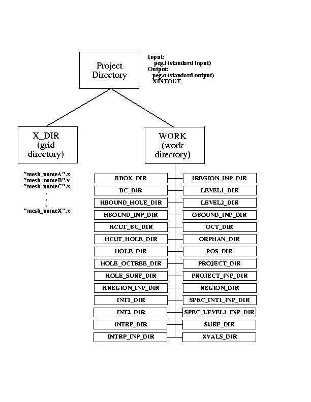
PEGASUS stores its files and information in a specific directory structure which it will create when it is first executed in a particular project directory. These directories can also be created in advance using the make_WORK script, which is also executed by the peg_setup script.
Execution of PEGASUS must be performed in the project directory
(see Figure 10). The user must supply the standard input file,
see Section 3.2 for input descriptions) and the
individual volume grids. The individual volume grids are stored in
the X_DIR directory as unformatted, single-zone, PLOT3D grid files.
These grid files are named "mesh_nameA.x", "mesh_nameB.x", etc, where
mesh_nameA, mesh_nameB, ... correspond to the NAME variables in the
$MESH namelists.
| PEGASUS 5 User's Guide | ||
| Previous Section | Table of Contents | Next Section |