Wing Body Example

A three-dimensional wing and fuselage. Contains 7 zones and 2.62 million grid points.

Download Example File


Input

NOTE: The minimal pegasus5 input file is that which is created by either the peg_setup script or the peg_in script. This minimal input file contains the $GLOBAL, $MESH, and $BCINP namelists, which, at a minimum, contain all the mesh names and all the boundary conditions for the flow problem.

For this case, three changes were made to the minimal input file. The first change was to increase the value of OFFSET to 2 in the MESH input for "body", "boxbody", "boxwing", and "boxouter". The second change was to add YSYM=1 to the BCINP namelist for the mesh "body". (This YSYM step will be automated in a future release).

Finally, the last change was to add a manual hole cutter to trim away the part of the outer region of the collar grid "wingcol" which wraps over to the opposite side of the the symmetry plane. This was done using the $BOUNDARY and $SURFACE namelists:


 $BOUNDARY NAME = 'collartrimmer',
   ISPARTOF = 'boxouter', 
   MHOLEIN = 'wingcol',
   CLOSED=.F.,
                                $END
      $SURFACE ISPARTOF = 'collartrimmer',
         JRANGE =   1, -1,
         KRANGE =   2,  2,
         LRANGE =   1, -1,
         NVOUT = '+K',
                                $END

A more efficient way to do the same thing would be to use the $BOUNDARY and $BOX namelists to define a volume in x,y,z space in which all points are to be cut away:


 $BOUNDARY NAME = 'collartrimmer',
   MHOLEIN = 'wingcol',
                                $END
      $BOX ISPARTOF = 'collartrimmer',
         XRANGE = -1.0, 1.0,
         YRANGE = -0.1, 0.05,
         ZRANGE = -1.0, 1.0,
                                $END

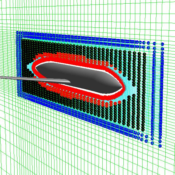
Images

  • Blue grid lines: body grid

  • Cyan grid lines: boxbody grid

  • Red symbols: points receiving data from body

  • Black symbols: points receiving data from boxbody

  • Blue symbols: points receiving data from boxouter

    NOTE: the input file specifies OFFSET=2 for all three of the box grids to ensure that the box-grid fringe points are not too close to the solid walls.

  • Cyan grid lines: boxbody grid

  • Green grid lines: boxouter grid

  • Red symbols: points receiving data from body

  • Black symbols: points receiving data from boxbody

  • Blue symbols: points receiving data from boxouter
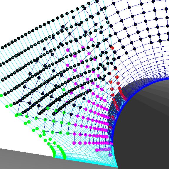
View looking downstream near the wing-body junction

  • Blue grid lines: body grid

  • Cyan grid lines: collar grid

  • Red symbols: points receiving data from body

  • Green symbols: points receiving data from wing

  • Magenta symbols: points receiving data from collar

  • Black symbols: points receiving data from box grids
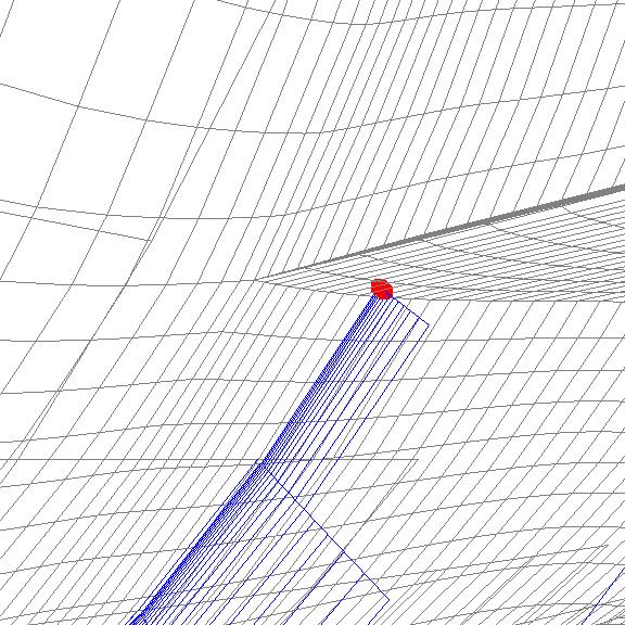
Automatic hole-cutting failure: This shows some points in the body grid which are inside the trailing-edge of the grid which do not get blanked out by the automatic hole-cutting algorithm. Even with OFFSET=2 used in the body grid, five ORPHAN points remain inside the wing.

  • Blue grid lines: body grid

  • Red symbols: ORPHAN points from body grid, which are inside the wing trailing edge

These points can readily be fixed by adding the following lines to the input file, and re-running pegasus5. This will manually blank out these points from inside the wing. This step is left as an exercise to for a new user of PEGASUS; this restart run should only take a few seconds to execute if pegasus5 has already been run with the supplied input file.


 $REGION NAME = 'body_cut',
   ISPARTOF = 'body',
   TYPE = 'HOLE',
   $END
 $VOLUME ISPARTOF = 'body_cut',
   JRANGE = 79, 79,
   KRANGE = 26, 26,
   LRANGE = 1,  26,
   $END