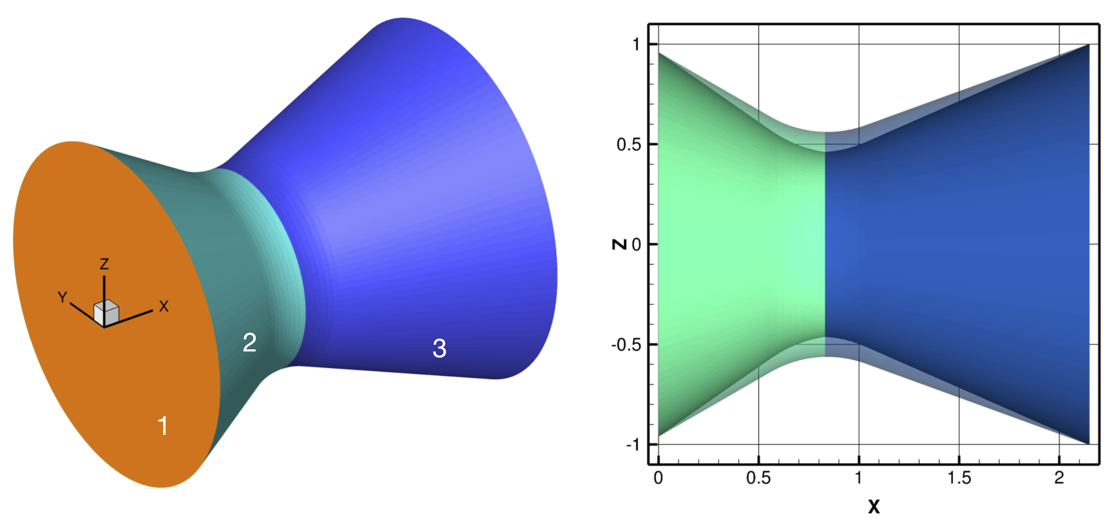
The new command line argument -sD NAME "FUNCTION" modifies the position of vertices of the input triangulation by using user-specified functions. The argument NAME is a string. The argument FUNCTION is a math expression. The value of the FUNCTION is assigned to its NAME. The symbols x, y and z are reserved keywords. They represent vertex coordinates of the input triangulation. For example, the command
% trix -sD x "x+2" file.tri
shifts all x-coordinates by two units to the right. Multiple -sD NAME "FUNCTION" arguments may be specified. For example,
% trix -sD x "x+2" -sD y "y+1" file.tri
Multiple -sD arguments are parsed left-to-right, which allows the user to define working (or temporary) variables. For example, consider a simple nozzle geometry consisting of three labeled components shown in the figure below. Component "1" is the "plenum" face, component "2" is the converging section of the nozzle and component "3" is the diverging section. The command
% trix -v -select 2 3
\
-sD deltaTR "-0.1" \
-sD throatX "8.3022118e-01" \
-sD theta "atan2(z,y)" \
-sD r "sqrt(z^2+y^2)" \
-sD tc "(x-xmin)/(throatX-xmin)" \
-sD td "1. - (x-throatX)/(xmax-throatX)" \
-sD Rc "r+deltaTR*tc" \
-sD Rd "r+deltaTR*td" \
-sD z "x-throatX > 0 ? Rd*sin(theta) : Rc*sin(theta)" \
-sD y "x-throatX > 0 ? Rd*cos(theta) : Rc*cos(theta)" \
nozzle.tri
linearly deforms the nozzle surface to reduce the throat radius by 0.1, as shown in the right frame of the figure. Use
% trix -helpSymbolic -helpVariable
for definition of supported operators, math functions and all reserved keywords, such as xmin and xmax used above.
The new command line argument -sT NAME "FUNCTION" is a sibling of the deformer option -sD described above. It allows manipulation of triangle labels, e.g., Component ID's, through use of user-specified functions. The primary keyword is 'tag', which represents the Component ID of each triangle. For example,
% trix -sT tag "(tag==3) ? 5 : tag" file.tri
changes triangles with component label 3 to 5 and keeps all others the same. Frequently, we wish to tag a region of the geometry as a unique component. This can be accomplished by using a command such as
% trix -sT tag "(x>0 && x<10) ? maxtag+1 : tag" file.tri
which relabels all triangles with vertices that have x-coordinates between 0 and 10 as a new component. Note the keyword 'maxtag', which holds the highest component tag of the input triangulation. Another example of tagging a region is the command
% trix -sT tag "(x^2+y^2+z^2 <= 1) ? maxtag+1 : tag" file.tri
which tags a region of the input triangulation that is contained within a sphere of unit radius as a new component.
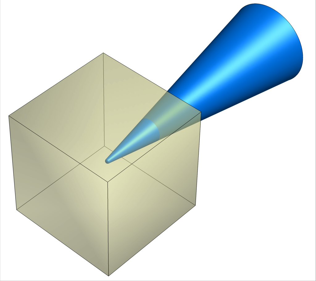
% trix -tagRegion XMIN XMAX YMIN YMAX ZMIN ZMAX file.i.tri
The command line argument tagRegion assigns a new tag to the wetted surface contained within a specified rectangular cuboid. This is illustrated in the frame on right, where the tip region of the cone contained within the cube would be tagged with a unique ID. The rectangular region is specified via its min and max corners XMIN XMAX YMIN YMAX ZMIN ZMAX. The new tag index is selected automatically as the next highest available component in the input triangulation.
% trix -cx XT -cy YT -cz ZT -rg XH YH ZH ANG file.i.tri
To rotate the geometry about an arbitrary axis, use the general rotation argument rg in conjunction with the center of rotation flags cx cy cz. The tail of the rotation vector is specified by XT YT ZT, the head by the first three arguments of rg XH YH ZH, and the rotation angle in degrees is the fourth argument ANG.
% trix -select 1 2 5 -x 2 file.i.tri
Previous versions of trix applied geometry manipulations, such as translations and rotations, to the entire triangulation. The new select command line argument lifts this restriction. When select is specified, the geometry manipulations are applied to the selected components only. For example, the command above moves components 1, 2 and 5 by two units in the x-direction. A practical example is manipulating control surfaces within a configuration, as illustrated in the animation below. Here, rotations about specified axes are used to move the control surfaces without needing to first separate the components.

To see all options and more details:
% trix -help
or just
% trix -
(top)