
Component labels are a basic element of Cart3D triangulations, where they indicate which component of a configuration a triangle belongs to. In practice, labels are simply integers assigned to the triangles. A basic example is shown on the right where each triangle pair belonging to the same face of a cube is assigned the same integer (denoted by the same color). Such labels not only identify components, but are also useful for specifying power boundary conditions and for defining aerodynamic components, sub-components, or even arbitrary regions of the geometry for force and moment integration. Recently new options have been added to provide greater flexibility when working with labels. Specifically, the new options preserve labeling within each watertight component and allow them to pass transparently through the intersect procedure. Historically, labeling an arbitrary region of the geometry was possible only after the intersect step. Here we show how to label a region of a watertight component before extracting the wetted surface with intersect. These features are supported in Cart3D v1.4.5 and newer.
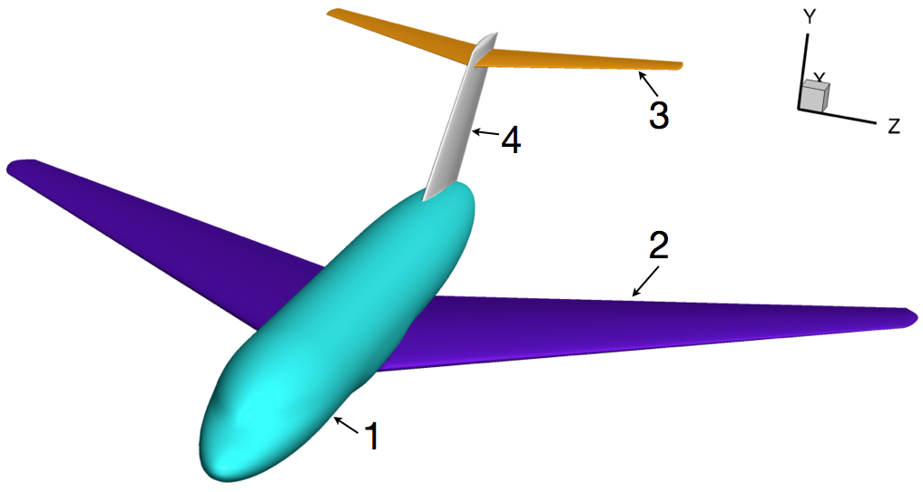 Let's assume you have been doing flow analyses on a wing-body-tail
configuration shown in the figure on the left. The geometry file is in the
standard wetted
surface triangulation format, where the fuselage, wing and tail components
have been intersected and are labeled as indicated. For example, you may have
been using these labels to specify force and moment integrations via
the Geometry
Manipulation Protocol (GMP)
and CLiC.
Frequently, we want to add additional labels to a configuration such as this
(maybe to specify surface boundary conditions) or to modify or remove existing
labels.
 To demonstrate, let's add "engines" and "pylons" to this configuration. We'll
add a total of four components (2 engines + 2 pylons) as shown in the figure on
the right. Assume that we are given a single engine and pylon in separate files
and that each is a watertight, standard
single component (there are either no labels or all triangles have the
same label). We will mirror the parts later to create a symmetric
configuration. A translucent side-view of the engine is shown in the inset
frame. The diffuser terminates at a fan-face inlet and the nozzle begins at a
power (exhaust) face
where surface boundary conditions will be applied.
The first step is to label the fan and power faces uniquely. Then
the SurfBC token
in input.cntl
can be used to specify appropriate boundary conditions for the simulation.
A convenient
approach is to use the utility code breakTris, which assigns a label
to a region of the triangulation surrounded by "sharp" edges. The user specifies
a seed triangle index, e.g. a triangle belonging to the fan face, and
optionally a sharpness threshold, and breakTris automatically labels
all triangles in the same region with a unique label. Multiple seeds can be
specified to generate multiple labels. We use the following command line to
label the fan and power faces:
Any triangle on the fan and power faces can be used as seed. Overgrid, Tecplot and Paraview are all convenient tools for finding seed indices (in this case triangles 14435 and 13839). In Overgrid this is done by pressing the f key while hovering over a triangle. By convention, we use the extension .i.tri for the output file to denote that the file now contains a watertight wetted surface triangulation with multiple components (just like the wing-body-tail configuration above).
 This "labeling step" adds new tags to the engine triangulation. A
cut-away view of the tagged engine
is shown on the left, where the nacelle (gray) is labeled as component 1, fan
face (blue) as component 2 and power face (red) as component 3. Notice that
for the integration of aerodynamic forces, you may wish to label the
diffuser and nozzle sections of the nacelle as separate components as well.
The engine is now ready for volume meshing and flow analysis. An excellent tutorial on isolated engine simulations is provided in $CART3D/doc/powerBCs/ which is also availible on-line. For further information on using trix or breakTris see the Cart3D Command Summary in $CART3D/doc/COMMAND_SUMMARY.pdf If you're working with CAD parts via Engineering Sketch Pad (ESP) or OpenCSM, both the OpenCSM scripting language and the egads2cart utility (included with ESP) can create face lables when the triangulation is generated on the CAD part. The same is true if you're generating geometry with Pointwise, or with OpenVSP. In addition, the Cart3D utility code triangulate can also assign face labels if given a component list file ( % triangulate -C Components.list ... ).
To generate an intersected watertight configuration consisting of engines, pylons and the wing-body-tail geometry, we need to differentiate between the existing labels, e.g. the fan, power or fuselage labels, and the traditional component labels that indicate watertight triangulations for processing by intersect. In other words, the key is to realize that we are intersecting three watertight triangulations — engine, pylon and wing-body-tail — some of which contain many face labels. We introduce two terms to clearly distinguish the label type:
There are two codes that manipulate face labels: trix and comp2tri. These codes offer many labeling options and we demonstrate only the critical ones here. As with all codes in Cart3D, a trailing dash "-" gives full usage statements, e.g. "% trix -" or "% comp2tri -". There are three steps to obtain a cubes-ready geometry.
The first step is to promote the existing labels of the wing-body-tail
triangulation to GMPtags via trix:
and similarly for the engine:
Note that trix automatically appends the .tri extension to
output files. The output files are written in in an extended triangulation
format (called "TRIX") that allows arbitrary triangle and vertex
data. Syntactically, this format it is subset of
the VTK Unstructured Grid XML
(VTU) format. This compatibility means that vtk-based tools such as
as Paraview and VisIt can read these files
natively. Alternatively, they can be converted for visualization
in Tecplot using "% trix -T ...". Native support for TRIX
files is planned for an upcoming release of Overgrid.
If we think ahead to the final geometry we wish to analyze in flowCart, we recognize that GMPtags from different triangulations may not be unique. For example, the wing in the wing-body-tail geometry is labeled as 2, which is the same as the fan face of the engine. The simulation would not go well if inlet boundary conditions are assigned to both the fan face and the wing. The user has the option to relabel manually or use the flag gmpTagOffset in comp2tri, which assigns unique labels automatically. We show the manual approach here and outline the automatic approach in the next section.
Let's assume that we wish to keep the wing-body-tail labels unchanged (1
through 4), and shift the engine labels from 1-3 to 5-7. This is accomplished
via trix:
which increments all engine GMPtags by 4, resulting in the nacelle
being labeled as 5, fan face as 6 and power face as 7. Now we deal with the
technicality that we wish to build a symmetric configuration with engines and
pylons on both sides. We use trix with the
option mirror Z to create a new component
mirrored about the Z plane. If required, trix also includes options to
scale, translate and rotate the geometry.
The same steps are repeated with the pylon, except that we use "-add2gmp
7" to shift its GMPtag past the engine power face
label. We are now ready to assemble and intersect the components.
Assembly of the configuration triangulation is done with comp2tri:
engine_gmp_shift4.i.tri engine_mirror.i.tri pylon_shift7.i.tri pylon_mirror.i.tri
which generates the familiar Components.tri file (written in extended
triangulation format). We finish with intersect:
to obtain the
final wetted surface
in Components.i.tri
with both IntersectComponents (ComponentIDs) and GMPtags.
The GMPtags of the final configuration are shown below, where
the face labels of the original wing-body-tail geometry are preserved (1-4),
the engines use labels 5 through 7 and the pylons are tagged with 8. These
labels can be used in your
Config.xml
file, as well as in
input.cntl
to specify SurfBC boundary conditions.

Recall that Components.i.tri also contains IntersectComponents. The image below shows the IntersectComponent labels assigned by comp2tri. These labels identify the 5 individual watertight component triangulations that were processed by intersect. Labels are assigned in the same order as the components appear in the comp2tri command line above.
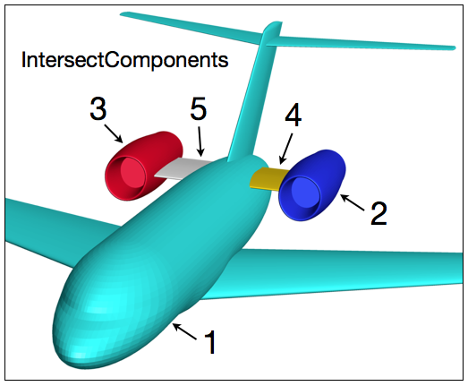
Earlier, we mentioned that it was possible to
skip the manual labeling in Step 2 and have
unique labels assigned automatically. This can be accomplished with the following
command:
engine_gmp.i.tri engine_mirror.i.tri
pylon.a.tri pylon_mirror.a.tri
where gmpTagOffset offsets the face labels found in each input file on the command line by a specified factor. In this case we use 4 because this is the highest GMPtag in all the triangulations, which causes the GMPtags found in the first file on the command line to be left unchanged, adds 4 to each GMPtag in the second file, adds 8 to each GMPtag in the third file, and so on to avoid label collisions. If an input file does not contain GMPtags, e.g. a single component triangulation such as the pylon, then comp2tri automatically assigns the next sequential label.
Note that intersect generates Components.i.tri in the
extended triangulation format. Many codes in the Cart3D package are
able to read and write these files,
including autoInputs, cubes and aero.csh. One of the
current exceptions is mpi_flowCart (as of release v1.4.7). If your work-flow
uses mpi_flowCart, then you can convert the triangulation file
back to the
standard wetted
surface triangulation format via trix:
which preserves the GMPtags of the configuration.
